Understanding Wiring Diagram Symbols
Which of the above is the symbol for field Line diagrams provide a fast, easy understanding of the connections and
New Wiring Diagram Auto Electrical diagram diagramtemplate diagramsample Electrical

13 rows a list of component descriptions and diagram symbols can be found on the electrical components.

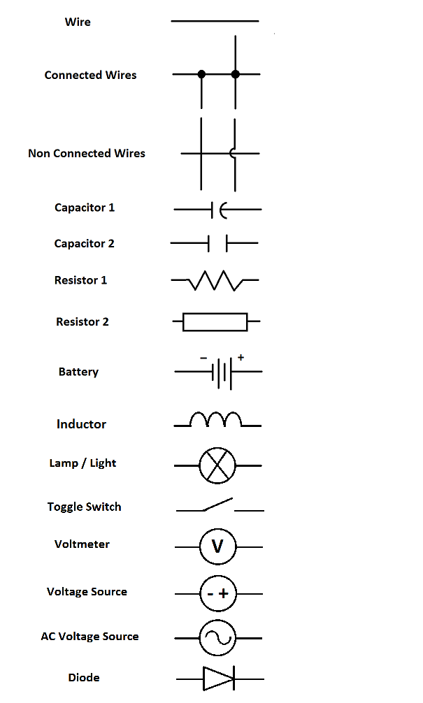
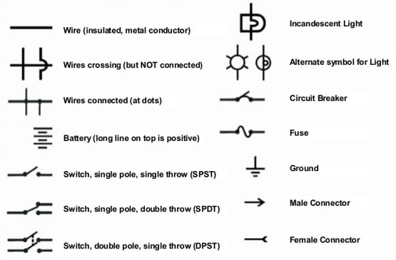
Understanding wiring diagram symbols. Power supply (positive from battery) fuse (protects the circuit from overload) switch (manual or controlled) load (light bulb, motor etc.) ground (return path to negative side battery) To read and understand an electronic diagram or electronic schematic, the basic symbols and conventions must be understood. Line diagrams a line (ladder) diagram is a diagram that shows the logic of an electrical circuit or system using standard symbols.
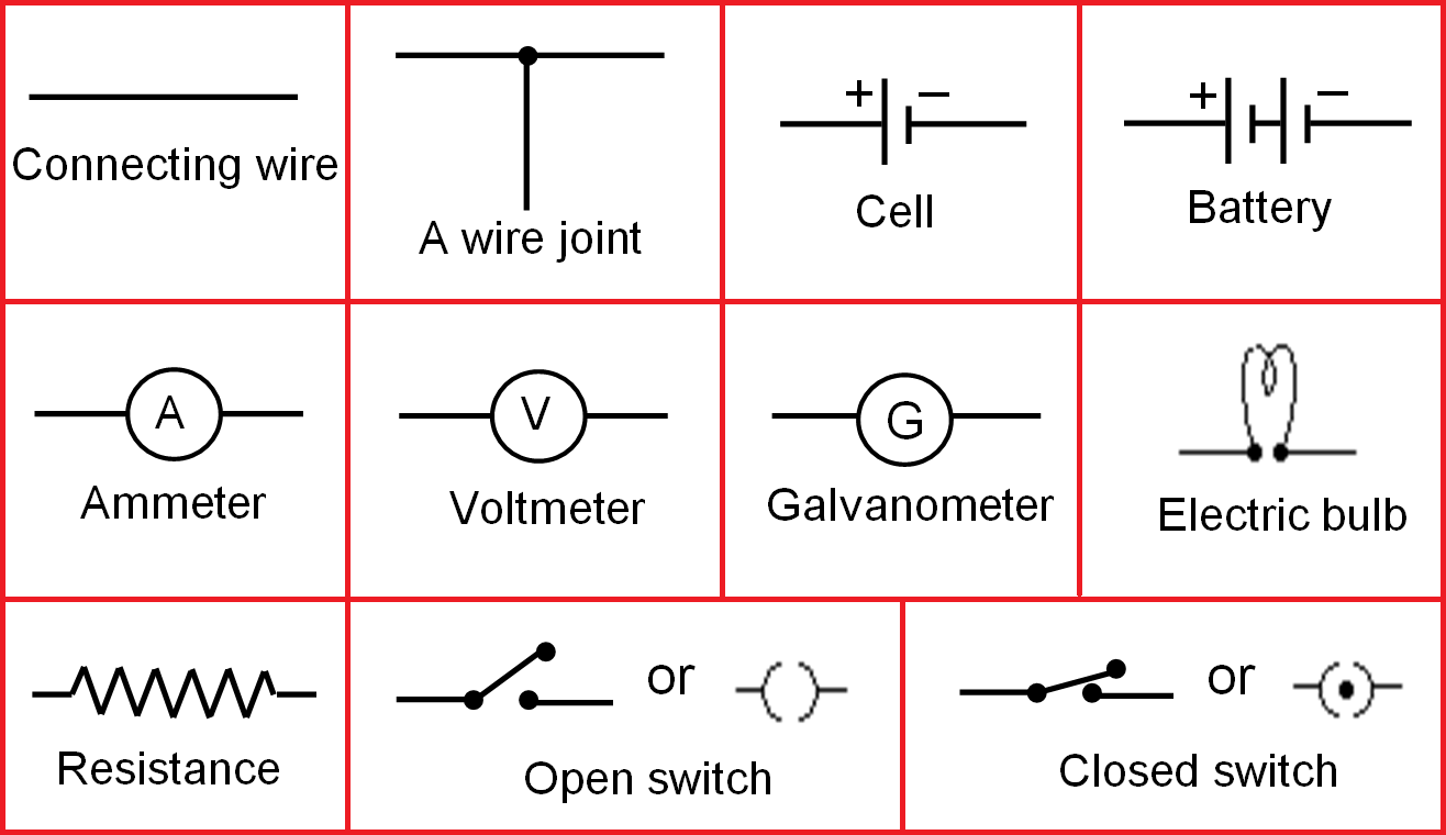
Wiring diagrams and symbols for home electrical wiring not only do wiring symbols show us where something is to be installed but what the electrical device is that will be installed. (1) switch, (2) battery, (3) resistor and (4) ground. By the way, color codes for electrical wiring are defined in din 47 002.
Since three phase devices can be connected in a delta, phase to phase connection,. Next, you need to identify how the symbols are connected and how to figure out their connections. A resistor will be represented with a series of squiggles symbolizing the restriction of current flow.
Schematic diagrams document the connection points and construction methods of electrical and electronic circuits. Nets are represented as lines between component terminals. Use the wire color in the wiring diagram to double checkthat you are looking at the correct pin.
The wiring diagram shows different components in a circuit via different shapes and symbols. Understanding the representation of symbols and components is just the primary stage in reading electrical schematics. To begin understanding how to read and understand electrical.
A line diagram is used to show the relationship between circuits and their components but not the actual location of the components. To understand how to read ladder wiring diagrams, let's start with a simple electrical schematic consisting of a power supply, switch, and light, then you will move on to our control panel sample wiring diagrams. The first and most common is the ladder diagram, so called because it looks like the symbols that are used to represent the components in the system have been placed on the rungs of a ladder.
These diagrams are an effective way of showing how wires are interconnected with different components in a system. Elementary diagram connections wire numbering. Understanding which components are which on a schematic is more than half the battle towards comprehending it.
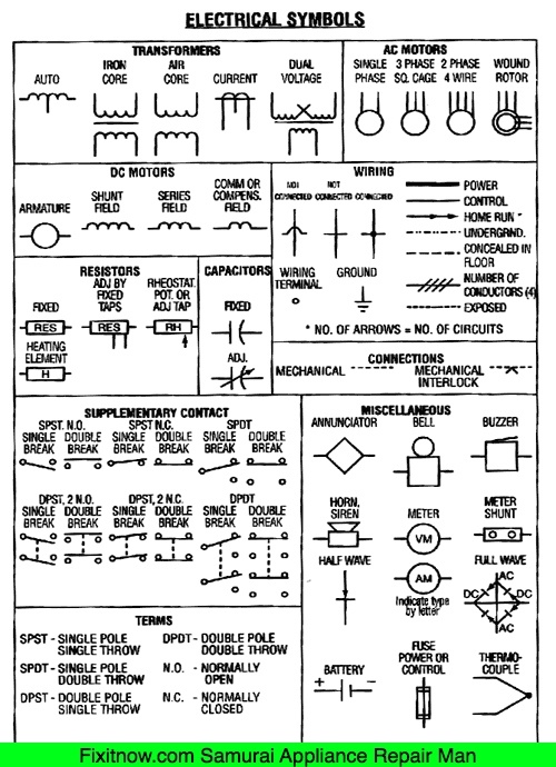
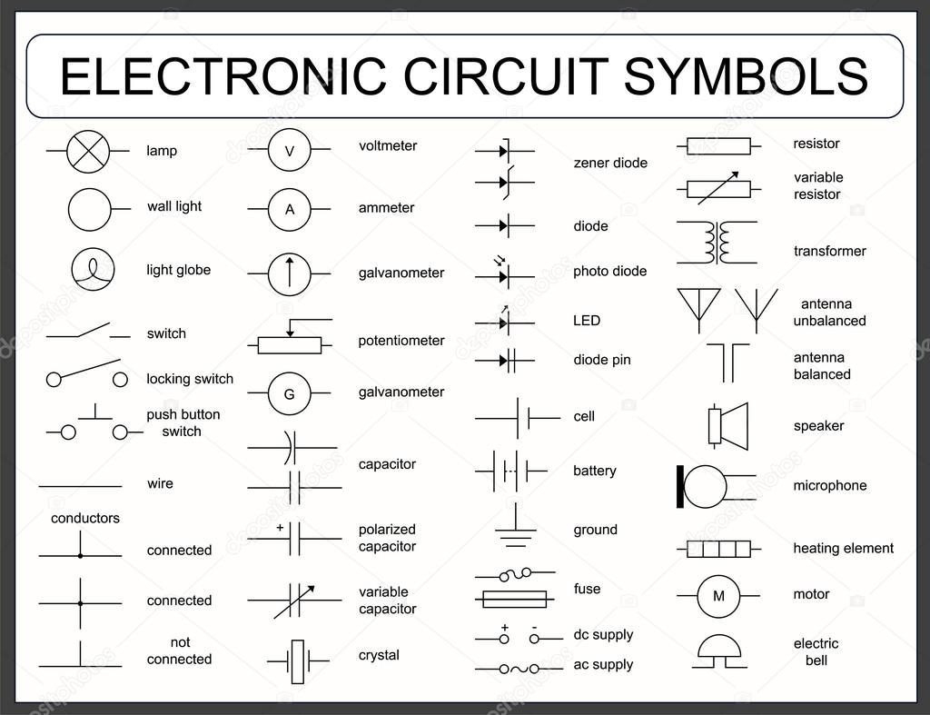
The standard or fundamental elements used in a wiring diagram include power supply, ground, wire and connection, switches, output devices, logic gate, resistors, light, etc. A typical basic circuit consists of five important parts: Single phase equipment may have the same symbol as a three phase device but will be specifically designated with the phase to which it is connected.
Understanding electrical diagrams rv 7.11.19 5 quiz 3: Most symbols used on a wiring diagram look like abstract versions of the real objects they represent. For example, a few basic symbols common to electrical schematics are shown as:
Schematic nets tell you how components are wired together in a circuit. A wiring diagram is simply a pictorial representation of all the electrical connections in a specific circuit. To read a wiring diagram, you should know different symbols used, such as the main symbols, lines, and the various connections.
Now all that remains is identifying how all of the symbols are connected together. Figure 2 shows the symbols for such basic components as wires and understanding and using electronic diagrams Eo 1.1 identify the symbols used on engineering electronic block diagrams, prints, and schematics, for the following components.
Automotive electrical diagrams provide symbols that represent circuit component functions. On it you can see some of the conventions used. Wiring diagrams and symbols for electrical wiring commonly used for blueprints and drawings not only do wiring symbols show us where something is to be installed, but what the electrical device is that will be installed.
For example, a switch will be a break in the line with a line at an angle to the wire, much like a light switch you can flip on and off. Note the switch symbol displays an open or closed circuit path, which is what an actual switch performs. On these diagrams the three phase equipment and connections are shown with a single line, thus the basis for the diagram name.
Types of wiring diagrams there are three basic types of wiring diagrams used in the hvac/r industrytoday. Symbols and abbreviations used in the schematic mean.
How to Read a Schematic

Ladder Wiring Diagram Symbols Devices Symbols And Circuits Reading And Understanding Ladder

Fundamentals to understanding automobile electrical and vacuum diagrams Old School Automotive

Wiring Diagram Symbols Legend, http//bookingritzcarlton.info/wiringdiagramsymbolsleg… Home

Automorive Wiring Diagram Schematic Symbols Legend Wiring Forums

Pin by David B. on Electronics Projects Electronic schematics, Electric circuit, Electrical

Electric Circuit and Circuit Diagram Fun Science
Understanding Wiring Diagram Symbols

Electrical Symbols on Wiring and Schematic Diagrams Samurai Appliance Repair Man
Wiring Diagram Symbols Wiring Diagram
Wiring Diagram Symbols Chart, http//bookingritzcarlton.info/wiringdiagramsymbolschart

23 Best images about Electrical on Pinterest Circuit diagram, Technology and Diy electronics

18 Clever Electrical Wiring Diagram Symbols List Technique, http//bookingritzcarlton.info/18c

Electrical Wiring Diagram Symbols Pdf Home Wiring Diagram
Auto Wiring Symbols Devices Symbols And Circuits Reading And Understanding Electrical Drawings
Electrical Wiring Diagram Symbols Pdf Home Wiring Diagram
Electrical Schematic Symbols Names And Identifications
Electrical Wiring Diagram Legend, http//bookingritzcarlton.info/electricalwiringdiagramlege
A Beginner’s Guide to Circuit Diagrams » Electrical Engineering Schools